How Can I Slow Down a 24 Volt Antenna Rotor
Having ii or more Arduino boards be able to communicate with each other wirelessly over a distance opens lots of possibilities like remotely monitoring sensor data, controlling robots, home automation and the list goes on. And when information technology comes down to having cheap yet reliable 2-fashion RF solutions, no one does a better chore than nRF24L01+ transceiver module from Nordic Semiconductor.
nRF24L01+ (plus) transceiver module tin can often be obtained online for less than two dollars, making it one of the most inexpensive data communication options that you can go. And best of all, these modules are super tiny, allowing y'all to contain a wireless interface into almost any project.
Hardware Overview
Radio Frequency
The nRF24L01+ transceiver module is designed to operate in 2.4 GHz worldwide ISM frequency band and uses GFSK modulation for information manual. The information transfer charge per unit tin can be one of 250kbps, 1Mbps and 2Mbps.
What is two.4 GHz ISM band?
ii.4 GHz band is one of the Industrial, Scientific, and Medical (ISM) bands reserved internationally for the utilize of unlicensed low-powered devices. Examples are Cordless phones, Bluetooth devices, near field communication (NFC) devices, and wireless figurer networks (WiFi) all utilise the ISM frequencies.
Power consumption
The operating voltage of the module is from 1.9 to 3.6V, merely the skillful news is that the logic pins are v-volt tolerant, then nosotros can easily connect it to an Arduino or any 5V logic microcontroller without using whatsoever logic level converter.
The module supports programmable output power viz. 0 dBm, -6 dBm, -12 dBm or -eighteen dBm and consumes unbelievably effectually 12 mA during transmission at 0 dBm, which is even lower than a unmarried LED. And best of all, it consumes 26 µA in standby mode and 900 nA at ability downwards mode. That's why they're the go-to wireless device for low-power applications.
SPI Interface
The nRF24L01+ transceiver module communicates over a 4-pin Serial Peripheral Interface (SPI) with a maximum data rate of 10Mbps. All the parameters such as frequency channel (125 selectable channels), output power (0 dBm, -six dBm, -12 dBm or -eighteen dBm), and data charge per unit (250kbps, 1Mbps, or 2Mbps) can exist configured through SPI interface.
The SPI bus uses a concept of a Master and Slave, in nigh common applications our Arduino is the Master and the nRF24L01+ transceiver module is the Slave. Unlike the I2C bus the number of slaves on the SPI charabanc is express, on the Arduino Uno yous can use a maximum of two SPI slaves i.e. two nRF24L01+ transceiver modules.
Here are complete specifications:
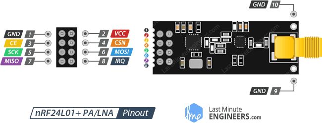
nRF24L01+ module Vs nRF24L01+ PA/LNA module
There are a variety of modules available based upon the nRF24L01+ scrap. Below are the most popular versions.
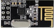
The first version uses on-board antenna. This allows for a more compact version of the breakout. However, the smaller antenna also means a lower manual range. With this version, you'll be able to communicate over a distance of 100 meters. Of course that is outdoors in an open up space. Your range indoors, especially through walls, volition be slightly weakened.
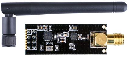
The second version comes with a SMA connector and a duck-antenna simply that'due south not the real departure. The real departure is that it comes with a special RFX2401C chip which integrates the PA, LNA, and transmit-receive switching circuitry. This range extender chip along with a duck-antenna helps the module achieve a significantly larger transmission range about 1000m.
What is PA LNA?
The PA stands for Power Amplifier. Information technology merely boosts the power of the signal beingness transmitted from the nRF24L01+ bit. Whereas, LNA stands for Depression-Racket Amplifier. The function of the LNA is to accept the
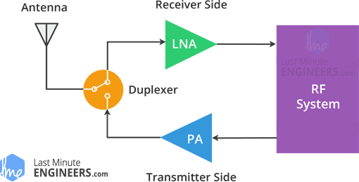
extremely weak and uncertain signal from the antenna (unremarkably on the gild of microvolts or nether -100 dBm) and amplify it to a more useful level (usually about 0.v to 1V)
The low-noise amplifier (LNA) of the receive path and the power amplifier (PA) of the transmit path connect to the antenna via a duplexer, which separates the two signals and prevents the relatively powerful PA output from overloading the sensitive LNA input. For more information bank check out this article on digikey.com
Except this difference, both modules are driblet-in compatible. Meaning, if y'all build your project with one you can just unplug it and use another without demand to make any changes to the organization.
How nRF24L01+ transceiver module works?
RF Channel Frequency
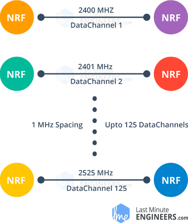
The nRF24L01+ transceiver module transmits and receives data on a certain frequency called Channel. Too in society for 2 or more than transceiver modules to communicate with each other, they need to be on the aforementioned channel. This channel could exist any frequency in the two.4 GHz ISM band or to be more than precise, it could be between ii.400 to two.525 GHz (2400 to 2525 MHz).
Each aqueduct occupies a bandwidth of less than 1MHz. This gives us 125 possible channels with 1MHz spacing. So, the module can use 125 different channels which requite a possibility to accept a network of 125 independently working modems in one place.
The channel occupies a bandwidth of less than 1MHz at 250kbps and 1Mbps air data rate. All the same at 2Mbps air data rate, 2MHz bandwidth is occupied (wider than the resolution of RF aqueduct frequency setting). And then, to ensure non-overlapping channels and reduce cross-talk in 2Mbps mode, yous demand to keep 2MHz spacing between 2 channels.
RF aqueduct frequency of your selected aqueduct is fix according to the following formula:
Freq(Selected) = 2400 + CH(Selected)
For example, if you select 108 as your channel for data transmission, the RF channel frequency of your aqueduct would be 2508MHz (2400 + 108)
nRF24L01+ Multiceiver Network
The nRF24L01+ provides a characteristic chosen Multiceiver. It's an abbreviation for Multiple Transmitters Unmarried Receiver. In which each RF channel is logically divided into 6 parallel data channels called Information Pipes. In other words, a information pipe is a logical channel in the physical RF Channel. Each information pipe has its own physical address (Information Pipe Address) and tin can be configured. This can be illustrated equally shown below.
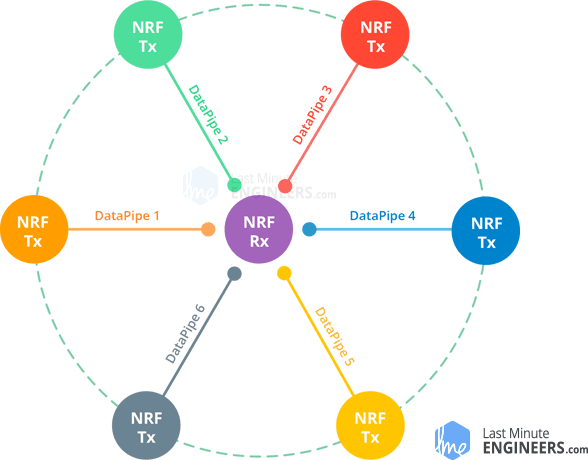
To simplify the above diagram, imagine the primary receiver interim equally a hub receiver collecting information from six dissimilar transmitter nodes simultaneously. The hub receiver can stop listening any time and acts as a transmitter. Merely this can only be done one pipage/node at a fourth dimension.
Enhanced ShockBurst Protocol
The nRF24L01+ transceiver module uses a packet structure known as Enhanced ShockBurst. This simple package structure is broken down into 5 dissimilar fields, which is illustrated below.
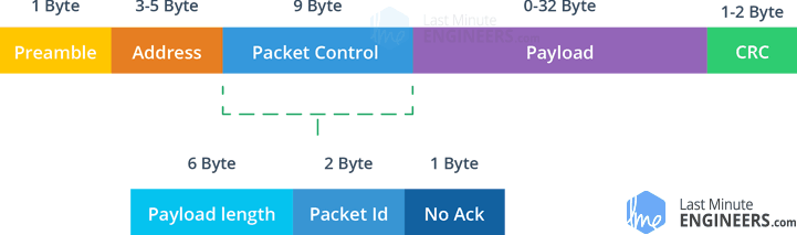
The original ShockBurst construction consisted only of Preamble, Address, Payload and the Cyclic Redundancy Cheque (CRC) fields. Enhanced ShockBurst brought about greater functionality for more enhanced communications using a newly introduced Packet Control Field (PCF).
This new structure is great for a number of reasons. Firstly, information technology allows for variable length payloads with a payload length specifier, meaning payloads tin vary from 1 to 32 bytes.
Secondly, it provides each sent packet with a bundle ID, which allows the receiving device to decide whether a message is new or whether it has been retransmitted (and thus can be ignored).
Finally, and well-nigh importantly, each message tin request an acknowledgement to be sent when it is received by some other device.
nRF24L01+ Automatic Packet Treatment
Now, permit'due south discuss three scenarios to go a better understanding of how two nRF24L01+ modules transact with each other.
Transaction with acknowledgement and interruptThis is an instance of positive scenario. Here the transmitter starts a advice past sending a data packet to the receiver. Once the whole package is transmitted, information technology waits (effectually 130 µs) for the acknowledgement bundle (ACK bundle) to receive. When the receiver receives the packet, it sends ACK packet to the transmitter. On receiving the ACK packet the transmitter asserts interrupt (IRQ) point to bespeak the new data is bachelor.
Transaction with data bundle lostThis is a negative scenario where a retransmission is needed due to loss of the packet transmitted. Afterward the packet is transmitted, the transmitter waits for the ACK packet to receive. If the transmitter doesn't get it within Auto-Retransmit-Delay (ARD) time, the parcel is retransmitted. When the retransmitted package is received by the receiver, the ACK parcel is transmitted which in turn generates interrupt at the transmitter.

Transaction with acknowledgement lostThis is again a negative scenario where a retransmission is needed due to loss of the ACK packet. Hither fifty-fifty if the receiver receives the bundle in the first attempt, due to the loss of ACK packet, transmitter thinks the receiver has non got the packet at all. And so, after the Auto-Retransmit-Delay time is over, information technology retransmits the bundle. At present when receiver receives the packet containing same packet ID as previous, it discards it and sends ACK package over again.
This whole packet handling is done automatically by the nRF24L01+ chip without involvement of the microcontroller.
nRF24L01+ Transceiver Module Pinout
Permit'southward have a look at the pinout of both the versions of nRF24L01+ transceiver Module.
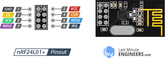
GND is the Ground Pivot. It is usually marked by encasing the pin in a square then it tin can be used equally a reference for identifying the other pins.
VCC supplies power for the module. This tin can be anywhere from one.9 to three.9 volts. You lot can connect it to 3.3V output from your Arduino. Remember connecting it to 5V pivot will likely destroy your nRF24L01+ module!
CE (Chip Enable) is an active-HIGH pin. When selected the nRF24L01 will either transmit or receive, depending upon which mode it is currently in.
CSN (Chip Select Not) is an active-Depression pin and is unremarkably kept Loftier. When this pin goes low, the nRF24L01 begins listening on its SPI port for information and processes information technology appropriately.
SCK (Series Clock) accepts clock pulses provided by the SPI motorcoach Principal.
MOSI (Master Out Slave In) is SPI input to the nRF24L01.
MISO (Principal In Slave Out) is SPI output from the nRF24L01.
IRQ is an interrupt pin that can alert the master when new data is available to process.
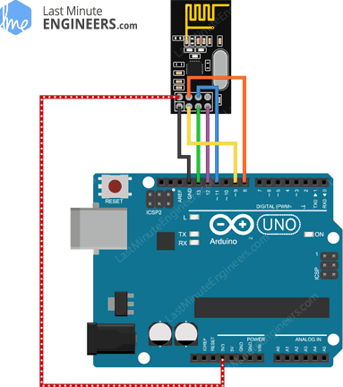
Wiring – Connecting nRF24L01+ transceiver module to Arduino UNO
Now that we have a complete agreement of how nRF24L01+ transceiver module works, we tin can begin hooking it up to our Arduino!
To start with, connect VCC pivot on the module to 3.3V on the Arduino and GND pin to ground. The pins CSN and CE can be continued to any digital pin on the Arduino. In our instance, it's connected to digital pivot#8 and #9 respectively. At present we are remaining with the pins that are used for SPI advice.
Equally nRF24L01+ transceiver module require a lot of data transfer, they will give the best performance when connected up to the hardware SPI pins on a microcontroller. The hardware SPI pins are much faster than 'flake-banging' the interface code using another set of pins.
Note that each Arduino Board has different SPI pins which should be continued accordingly. For Arduino boards such as the UNO/Nano V3.0 those pins are digital 13 (SCK), 12 (MISO) and 11 (MOSI).
If y'all take a Mega, the pins are different! You'll want to utilize digital fifty (MISO), 51 (MOSI), 52 (SCK), and 53 (SS). Refer below tabular array for quick understanding.
In example you're using dissimilar Arduino lath than mentioned to a higher place, it is appropriate to check the Arduino official documentation before proceeding.
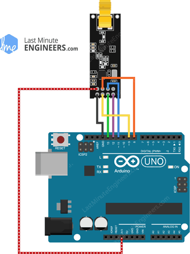
Remember! You demand to brand 2 of these circuits. One acts equally a transmitter and the other equally a receiver. The wiring for both is identical.
One time you lot take everything hooked up you lot are ready to get!
RF24 Arduino Library for nRF24L01+ Module
Interfacing with nRF24L01+ transceiver module is a agglomeration of piece of work, but luckily for u.s.a., there are a number of libraries available. One of the pop libraries is RF24. This library has been around for several years. Information technology is uncomplicated to apply for beginners, but yet offers a lot for advanced users. In our experiments, nosotros volition be using the same library.
You tin can download the latest version of library on the RF24 GitHub repository fork or, just click this button to download the zip:
To install it, open the Arduino IDE, get to Sketch > Include Library > Add .Nada Library, and so select the RF24-main file that you only downloaded. If you need more than details on installing a library, visit this Installing an Arduino Library tutorial.
Arduino Lawmaking – For Transmitter
In our experiment we will just ship a traditional 'Hello World' bulletin from the transmitter to the receiver.
Here is the sketch nosotros will be using for our transmitter:
//Include Libraries #include <SPI.h> #include <nRF24L01.h> #include <RF24.h> //create an RF24 object RF24 radio(nine, 8); // CE, CSN //address through which ii modules communicate. const byte address[6] = "00001"; void setup() { radio.begin(); //fix the address radio.openWritingPipe(accost); //Fix module every bit transmitter radio.stopListening(); } void loop() { //Ship message to receiver const char text[] = "Hello Earth"; radio.write(&text, sizeof(text)); filibuster(thousand); } The sketch starts by including the libraries. SPI.h library handles the SPI advice while nRF24L01.h and RF24.h controls the module.
//Include Libraries #include <SPI.h> #include <nRF24L01.h> #include <RF24.h> Adjacent, we need to create an RF24 object. The object takes two pivot numbers as parameters to which signals CE and CSN are continued.
//create an RF24 object RF24 radio(9, 8); // CE, CSN Next we demand to create a byte array which will represent the pipe accost through which two nRF24L01+ modules communicate.
//address through which ii modules communicate. const byte address[6] = "00001"; We can alter the value of this address to whatever 5-letter string such as "node1". The address is necessary if you have a few modules in a network. Thanks to the address, y'all can cull a detail module to which you are interested in communicating, so in our case nosotros will have the same address for both the transmitter and the receiver.
Side by side in the setup function: nosotros need to initialize the radio object using radio.brainstorm() and using the radio.openWritingPipe() office we set up the accost of the transmitter.
//set the address radio.openWritingPipe(address); Finally, we will utilize the radio.stopListening() part which sets module as transmitter.
//Set module as transmitter radio.stopListening(); In the loop section: we create an assortment of characters to which we assign the message "Hello Earth". Using the radio.write() role we will send that bulletin to the receiver. The first argument hither is the message that we want to ship. The second argument is the number of bytes nowadays in that message.
const char text[] = "Hello World"; radio.write(&text, sizeof(text)); Through this method, yous tin send up to 32 bytes at a fourth dimension. Considering that is the maximum size of a single package nRF24L01+ tin can handle. If you demand a confirmation that the receiver received data, the method radio.write() returns a bool value. If it returns True, the information reached the receiver. If it returns False, the data has been lost.
the radio.write() function blocks the program until it receives the acknowledgment or runs out of all attempts of retransmission.
Arduino Code – For Receiver
Hither is the sketch we volition exist using for our receiver
//Include Libraries #include <SPI.h> #include <nRF24L01.h> #include <RF24.h> //create an RF24 object RF24 radio(9, 8); // CE, CSN //address through which two modules communicate. const byte accost[6] = "00001"; void setup() { while (!Serial); Serial.brainstorm(9600); radio.begin(); //set the address radio.openReadingPipe(0, address); //Fix module as receiver radio.startListening(); } void loop() { //Read the data if bachelor in buffer if (radio.available()) { char text[32] = {0}; radio.read(&text, sizeof(text)); Serial.println(text); } } This plan looks quite like to the program of the transmitter except some changes.
At the get-go of the setup part we offset the serial advice. Next using radio.setReadingPipe() role nosotros gear up the same address every bit transmitter and in that mode nosotros enable the communication between transmitter and receiver.
//set the address radio.openReadingPipe(0, address); The first statement is the number of the stream. You tin create upwardly to 6 streams that respond to different addresses. We created only address for the stream number 0. The second argument is the address to which the stream will react to collect the data.
The next step is to set the module as a receiver and start receiving information. To exercise that nosotros use radio.startListening() function. From that moment the modem waits for data sent to the specified address.
//Ready module as receiver radio.startListening(); In the loop role: The sketch checks whether any data has arrived at the address using radio.bachelor() method. This method returns True value if we whatever information is bachelor in buffer.
if (radio.available()) { char text[32] = {0}; radio.read(&text, sizeof(text)); Serial.println(text); } If the data is received, then information technology creates an array of 32 characters filled with zeros (afterward the program will fill it with the received data). To read the data we use the method radio.read (& text, sizeof (text)). This will store the received data in to our character array.
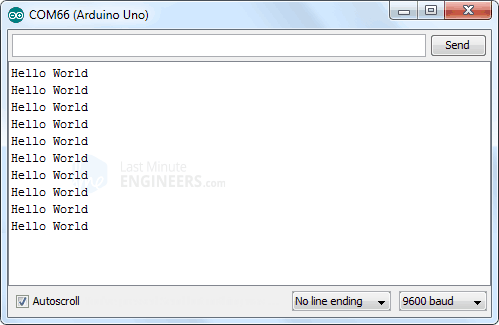
At the end we only print the received bulletin on serial monitor. If you did everything ok and there are no mistakes in connections, yous should see something like this in your Serial Monitor.
Improving range of nRF24L01+ transceiver Module
A central parameter for a wireless advice system is the advice range. In many cases it's the deciding gene for choosing an RF solution. And so, let's discuss what we tin can do to get a better range for our module.
Reduce Power Supply Racket
An RF excursion that generates a Radio Frequency (RF) signal, is very sensitive to power supply dissonance. If non controlled, the power supply noise can significantly reduce the range y'all can get.
Unless the power source is a stand up-lone battery, there is a good chance that there is noise associated with the generation of the ability. To prevent this noise from inbound the system, it is advised to place a 10 µf filter capacitor across the ability supply line as physically close to the nRF24L01+ module every bit possible.
An easiest style to get over with is to apply a very cheap Adapter Module for nRF24L01.
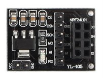
The adapter module has an eight-pin female connector to permit yous to plug in your nRF24L01 module. Information technology can accommodate both the module nosotros discussed before, the one with integrated antenna and other with external antenna (PA/LNA). Information technology as well has a 6-pivot male connector for the SPI and Interrupt connections and a 2-pin connector for power input.
The adapter module has its own 3.3 volt voltage regulator and a set of filter capacitors, and so you tin ability it with a five-volt power supply.
Change your channel frequency
Another potential source of racket for an RF circuit is the outside environment, especially if you have neighboring networks set on the same aqueduct or interference from other electronics.
To prevent these signals from causing problems, we propose using the highest 25 channels your nRF24L01+ module. Reason for this is WiFi uses most of the lower channels.
Lower Data Charge per unit
The nRF24L01+ offers highest receiver sensitivity at 250Kbps speed which is -94dBm. However at 2MBps data charge per unit, the receiver sensitivity drops to -82dBm. If you speak this language, you know that the receiver at 250Kbps is nearly 10 times more than sensitive than at 2Mbps. That means the receiver can decode a signal that is x times weak.
What does Receiver (Rx) sensitivity mean?
Receiver sensitivity is the everyman power level at which the receiver can observe an RF point. The larger the accented value of the negative number, the better the receiver sensitivity. For example, a receiver sensitivity of −94 dBm is improve than a receiver sensitivity of −82 dBm by 12 dB.
And then, lowering the data charge per unit can significantly improve the range y'all can achieve. Likewise, for most of our projects, 250Kbps speed is more than than sufficient.
College Output Power
Setting maximum output power can also improve the communication range. The nRF24L01+ lets you cull i of the output power viz. 0 dBm, -6 dBm, -12 dBm or -18 dBm. Selecting 0 dBm output power sends stronger bespeak over the air.
Source: https://lastminuteengineers.com/nrf24l01-arduino-wireless-communication/
0 Response to "How Can I Slow Down a 24 Volt Antenna Rotor"
Post a Comment